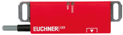
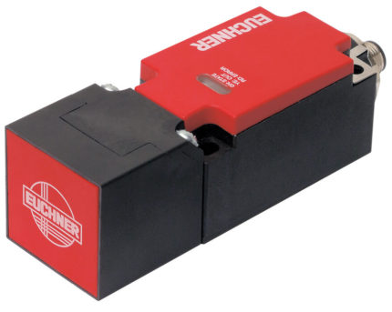
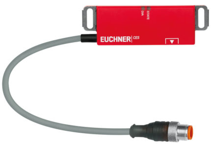
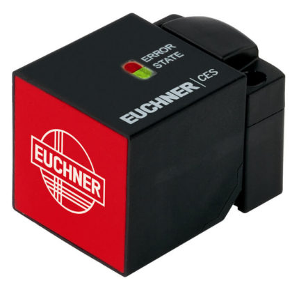
- Safety switch with guard locking and integrated evaluation electronics
- Short circuit monitoring
- Two safety outputs (semiconductor outputs)
- Up to category 4/PL e according to EN ISO 13849-1
- Two pushbuttons (illuminated)
- With plug connector M23
- Unicode
- Door monitoring output
- With escape release
- Approach directions A, B and C (delivery state)

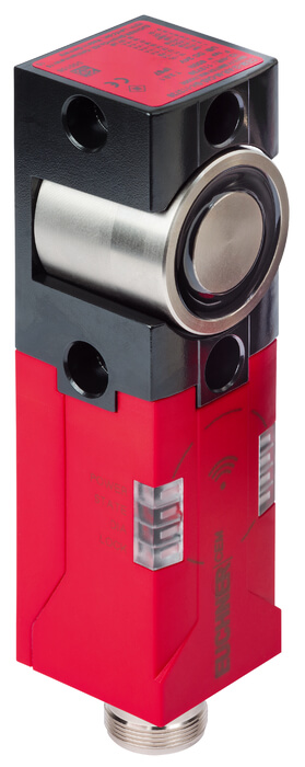
Euchner CTP-L1-AP-U-HA-AEE-SH-137342 CTP-AP safety switch with guard locking
Description
Additional information
| Brand |
|---|
GET A PRICE
To receive a proposal, please send your application to [email protected] and specify the required positions and company details.
Specification
Approach direction
Horizontal
Can be adjusted in 90° steps
Each actuator is unique. The switch detects only taught-in actuators. Additional actuators can be taught in. Only the last actuator taught in is detected.
Guard locking type
Lens set
The color of the pushbutton can be selected using the lens set included (five colors). Item no.: 120344 (see Accessories)
Connector assignment
Electrical connection ratings
Work area
Controls and indicators
Other
Reliability values according to EN ISO 13849-1
| CTP?L1 | Guard locking actuated by spring force applied and power-ON released (closed-circuit current principle) |
| Plug connector (view of connection side) | Pin | Designation | Function | Conductor coloring of connecting cable |
|---|---|---|---|---|
| 1 | IMP | Operating voltage of guard locking solenoid 24 V DC | VT | |
| 2 | - | Not used | RD | |
| 3 | - | Not used | GY | |
| 4 | FO1A | Safety output, channel 1 | RD/BU | |
| 5 | FO1B | Safety output, channel 2 | GN | |
| 6 | UB | Operating voltage of AP electronics, controls and indicators 24 V DC | BU | |
| 7 | RST | Reset input | GY/PK | |
| 8 | OD | Door monitoring output | GN/WH | |
| 9 | OI | Diagnostic output | YE/WH | |
| 10 | OL | Guard locking monitoring output | GY/WH | |
| 11 | - | Not used | BK | |
| 12 | FE | Function earth (must be connected to meet the EMC requirements) | GN/YE | |
| 13 | IMM | Operating voltage of guard locking solenoid 0 V | PK | |
| 14 | - | Not used | BN/GY | |
| 15 | S2 | Pushbutton 2 (illuminated) | BN/YE | |
| 16 | H2 | LED 2 | BN/GN | |
| 17 | S3 | Pushbutton 3 (illuminated) | WH | |
| 18 | H3 | LED 3 | YE | |
| 19 | 0 V UB | Operating voltage of AP electronics, controls and indicators 0 V | BN |
| Housing material | |
| Switch head cover | Die-cast zinc |
| Safety switch housing | Fiber glass reinforced thermoplastic |
| Weight | |
| Net | 0,5 kg |
| Ambient temperature | |
| At UB = 24V DC | -20 ... +55 °C |
| Degree of protection | IP65 |
| Resilience to vibration | In acc. with EN IEC 60947-5-3 |
| Mechanical life | 1 x 10⁶ |
| Installation orientation | Any |
| Ready delay | max.1 s |
| Switching frequency | max.0,5 Hz |
| Connection | 1 plug connector M23, 19-pin, RC18 |
| Approach speed | 20 m/min |
| Guard locking principle | Closed-circuit current principle |
| Locking force Fmax | 3900 N |
| Locking force FZh | 3000 N |
| Retention force | 20 N |
| Extraction force | 20 N |
| Actuating force | 10 N |
| Overtravel | 5 mm |
| Test-pulse interval | min.100 ms |
| Test pulses | max.0,3 ms |
| Operating voltage DC | |
| UUB | 24 V DC -15% ... 15% Reverse polarity protected, regulated, residual ripple < 5%, PELV |
| Current consumption | |
| IIMP | 400 mA |
| IUB | 40 mA |
| Utilization category according to EN 60947-5-2 | |
| DC-13 | 24V 150mA |
| Solenoid operating voltage DC | |
| UIMP | 24 V DC -15% ... +10% Reverse polarity protected, regulated, residual ripple < 5%, PELV |
| Fusing | |
| External (operating voltage UB) | 0,25 ... 2 A |
| External (solenoid operating voltage IMP) | 0,5 ... 8 A |
| Rated insulation voltage Ui | max.50 V |
| Rated impulse withstand voltage Uimp | max.0,5 kV |
| Power consumption | 6 W |
| EMC protection requirements | In acc. with EN IEC 60947-5-3 |
| Solenoid duty cycle | 100 % |
| Degree of contamination (external, according to EN 60947-1) | 3 |
| Safety class | |
| EN IEC 61140 | III |
| Switching load | |
| According to UL | 24V DC, class 2 |
| Safety outputs FO1A / FO1B | |
| Type of output | 2 semiconductor outputs, p-switching, short circuit-proof |
| Switching current | |
| Per safety output FO1A / FO1B | 1 ... 150 mA |
| Output voltage | |
| High U(FO1A) / U(FO1B) | UB-1,5 ... UB V DC |
| Low U(FO1A) / U(FO1B) | 0 ... 1 V DC |
| Off-state current Ir | max.0,25 mA |
| Switch-on time | max.400 ms |
| Discrepancy time | |
| Both safety outputs | max.10 ms In acc. with EN IEC 60947-5-3 |
| Monitoring output OL | |
| Type of output | p-switching, short circuit-proof |
| Switching current | 1 ... 50 mA |
| Output voltage | 0,8xUB ... UB V DC |
| Monitoring output OD | |
| Type of output | p-switching, short circuit-proof |
| Switching current | 1 ... 50 mA |
| Output voltage | 0,8xUB ... UB V DC |
| Monitoring output OI | |
| Type of output | p-switching, short circuit-proof |
| Switching current | 1 ... 50 mA |
| Output voltage | 0,8xUB ... UB V DC |
| Controls and indicators | |
| Operating voltage | UB V |
| Operating current | 1 ... 50 mA |
| Power supply | |
| LED | 24 V |
| Current consumption | |
| LED | 10 mA |
| Repeat accuracy R | 10 % |
| Position 2 | |
| Ausfuhrung | Illuminated push buttons |
| Einlegeschild | |
| Extras | |
| Farbe | |
| Schaltelement | 1NO |
| Position 3 | |
| Ausfuhrung | Illuminated push buttons |
| Einlegeschild | |
| Extras | |
| Farbe | |
| Schaltelement | 1NO |
| Additional feature | |
| Escape release actuated by pushing | |
| Incl. cover set ID. No. 120344 | |
| For the approval according to UL the following applies | Operation only with UL class 2 power supply, or equivalent measures see operating instructions |
| Performance Level | PL e |
| Category | 4 |
| PFHD | 4.1 x 10 -9 |
| Mission time | 20 y |